Introduction
This technical note provides details of the Nvelope framing system, the Nvelope Thermal Gasket, its R-value and its relevance to the NCC 2019 Section J.
Requirements of NCC 2019 Section J0.5(c).
As can be seen in J0.5 (a) a thermal break is required only where “a wall lining that is fixed directly to the same metal frame” is present.
J0.5 Wall thermal breaks
For compliance with J0.2(c), a wall that—
(a) does not have a wall lining or has a wall lining that is fixed directly to the same metal frame; and
(b) has lightweight external cladding such as weather-boards, fibre-cement or metal sheeting fixed to a metal frame, must have a thermal break, consisting of a material with an R-Value of not less than R0.2, installed at all points of contact
As can be seen in J0.5 (a) a thermal break is required only where “a wall lining that is fixed directly to the same metal frame” is present.
When using the Nvelope system there is no requirement for a thermal break under Section J0.5(c) because there is no single metal framing member of the Nvelope system that directly connects the wall cladding and the wall lining.
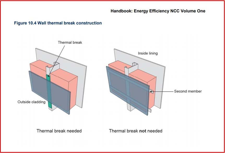
For further clarification we suggest reference is made to the NCC Volume One Energy Efficiency Provisions 2019 Handbook. See Figure 10.4 taken from this handbook.
We may not agree that the code is best practice for addressing thermal bridging, but as per the code, the need for a thermal break only applies if there is a single metal framing member that directly connects the wall cladding and the wall lining.
Performance and compliance
At DCTech we are focussed on introducing best practice systems and see the code as the very minimum.
The use of the Nvelope thermal isolator provides a thermal break between the Nvelope framing system and the structure and will improve the thermal performance of the building envelope.
The thermal isolator is not required to meet Section J0.5(c), but to enhance performance. Just because the performance improvement is not recognised in the NCC here in Australia, we do not see that as a reason not to use it.
Non-combustibility
The Nvelope thermal isolator is made from a plastic material so it is combustible. If the fire engineer deems that the Nvelope thermal isolator is not a “gasket” as listed in Part C1.9(d) or considers the isolator to represent an undue risk in the event of a fire then the thermal spacer can easily be removed from the Nvelope bracket without compromising compliance to Section J0.5(c). For thermal performance, however, we would much rather the thermal isolator stays.
 What is the R-value of the Nvelope Thermal Isolator
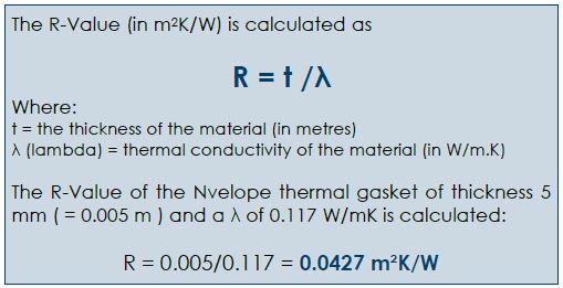
The R-Value refers to a material’s ability to resist heat transfer at a certain thickness – the higher the better when looking for an insulation material.
As can be seen, this is far lower than R0.2. Users could be forgiven for thinking that because it is less than R0.2, why even bother? It is important to realise that even though the thermal bridge is a small area relative to the entire façade, the addition of a thermal break still has a considerable impact on improving thermal performance and reducing condensation risk.
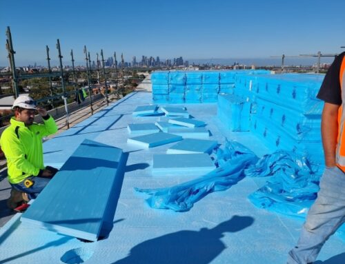
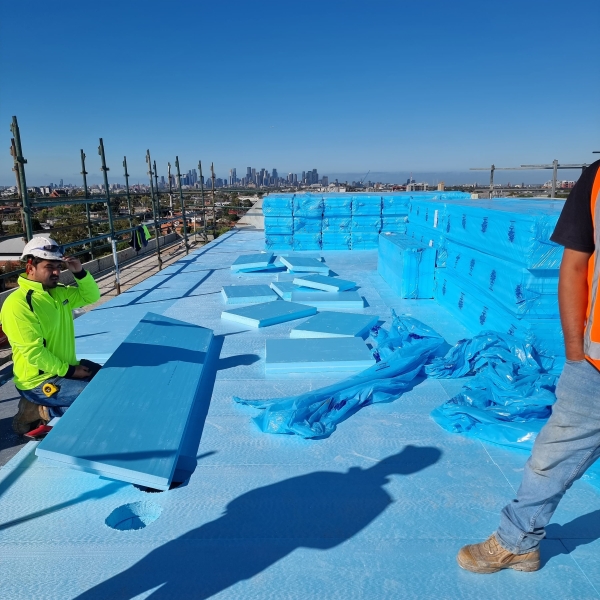
 Continuous insulation and external insulation.
Wherever possible we suggest building enclosures that manage thermal bridging, incorporate an effective air control layer and address condensation risk. For commercial non-combustible wall constructions please look for systems in our technical library that address continuous insulation and external insulation such as our wall system DCT-W23-3, shown here.
DCTech Nvelope 3D Thermal Bridging Service
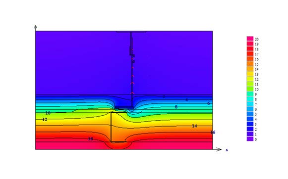
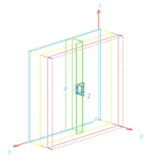
DCTech Nvelope can, on a project specific basis, offer a 3D thermal bridge modelling service. The construction is modelled into a 3-dimensional form to allow a distinct understanding of the geometry and effect of the intended materials. Nvelope brackets and fixings are modelled correctly with a point thermal transmittance (chi-value) calculated for the thermal bridge formed. The thermal calculation can accommodate specific materials or use generic values and be tailored to suit your project design. The result can be used for condensation risk assessment.


Leave A Comment
You must be logged in to post a comment.